Automatic monitoring and control system consists of 5 programmable logic controllers (PLC) and 1 panel computer with touch screen. Each controller provides monitoring and control functions for corresponding group of engineering equipment. Controllers are placed in control boxes:
- CM1 (Chiller 1) –control box of chiller supplying coolant for ice rink floor (big chiller);
- CM2 (Chiller 2) –control box of chiller supplying coolant for air handling unit
- Ice (SCHA-THS) –control box for circulation pumps (P1.1, P1.2, P2 and P3);
- Air (SCHA-PV1) –control box for Air Handling Unit (AHU);
- Snow (SCHA-SR) –control box for snow room equipment (snow makers and coolers).
Equipment for ice rink cooling Ice equipment is consists of:
- Chiller 1 (CM1);
- Main circulation pumps Р.1 and Р.2;
- Pump P2 of water heating tank for ice resurfacer machine; Pump P3 for dehumidifier preheater.
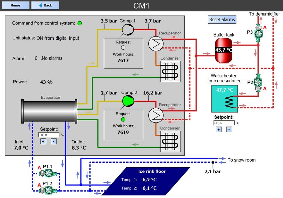 The main purpose of this system is to keep ice rink field temperature at the desired level. Secondary goal is to keep water temperature in heater tank for ice resurfacer.
Pumps P 1.1 and P1.2 is a pair of pumps. One of them is active and second is reserverd. Active and reserved pumps changes every 72 hours. Reserved pump will be activated when active pump is shut down. Resurfacer water heater pump P2 starts automatically when water temperature in heating tank is below setpoint. It stops if water temperature is above setpoint. Dehumidifier air preheater pump P3 starts and stops automatically at the same time as dehumidifier works.
Air handling
To handle air quality in ice rink room (temperature, humidity, CO2 concentration) such equipment is used:
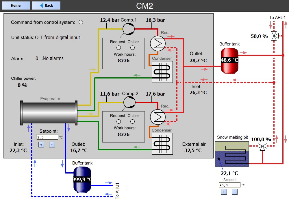
- Chiller 2 (CM2);
- Air handling Unit (AHU);
- Dehumidifier;
- Control valve of air heater in AHU;
- Pump P3 for dehumidifier reactivation air preheater (see page “Chiller 1”).
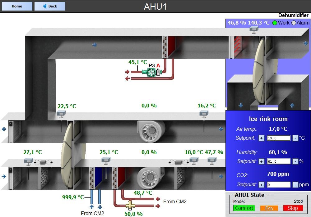 AHU contains air fans, dumpers, filters, cooler, heater and recuperator (rotor). It’s main goal is to keep air temperature and CO2 concentration in the room at the desired level (setpoint). C02 is regulated by variating fans speed, and room temperature is regulated by variating supply air temperature.
Fans can operate at different speed level. The speed of fans is automatically adjusted to keep concentration of CO2 in the room below the desired level. If CO2 is higher than setpoint, fan speed increased.
Dehumidifier is intended to use cold exhaust air for precooling of external air at the inlet of AHU. This method improves energy efficiency of AHU. Rotor is rotating all the time when AHU is on.
Air cooler is the main device to cool external air before supply it to room. The coolant is taken from Chiller 2.
Air heater and control valve is aimed to keep supplying air temperature at the desired level. Regulation of temperature is achieved by control valve. To make air temperature higher valve is opened automatically. Valve position 100% – is the maximum possible heating, 0% – heating is off.
State of filters is controlled by differential air pressure meters set up on filters (they measure difference of air pressure before and after each filter). If filter is dirty its pressure difference is high and alarm is shown on computer screen.
Dehumidifier is aimed to keep room air humidity at the desired level (setpoint). When air humidity is greater than setpoint dehumidifier is turned on by controller. When humidity is less then setpoint minus hysteresis (5%) it’s automatically turned off.
CM2 is supply cooling and heating liquids to air cooler and heater of AHU respectively.
Secondary goal is to heat snow melting pit. It’s temperature is regulated by control valve.
 User’s interface
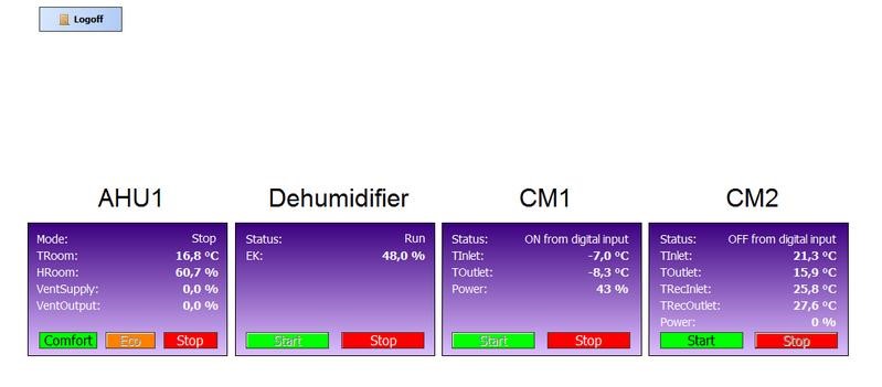
User interacts with system through graphical interface of panel computer (or web browser). Computer can show various kinds of data from monitored equipment:
- Current values of monitored parameters (temperature, pressure, humidity, etc.);
- Current state of each monitored device (pump, compressor, fan, etc.);
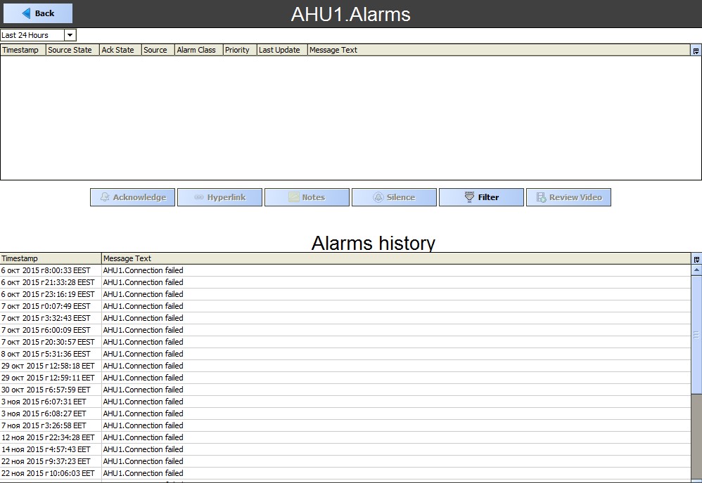
- Messages about dangerous situations (alarms); Historical data of all parameters and alarms.
With panel computer user can perform such actions:
- Change setpoint for any regulated parameter (for example, setpoint for chiller outlet temperature);
- Start and stop ice, air and snow systems;
- Reset alarms of pumps in ice system (alarms of chillers may be reset only from chiller’s local control box).
Graphical interface of system consists of several pages (such as “Home”, “Chiller 1”,
“Chiller 2”, “AHU1” and etc). Each of this pages contains information about respective equipment. On the “Home” page you can see the basic parameters of the system, and can also perform control equipment.
 Users can view history of any parameter.
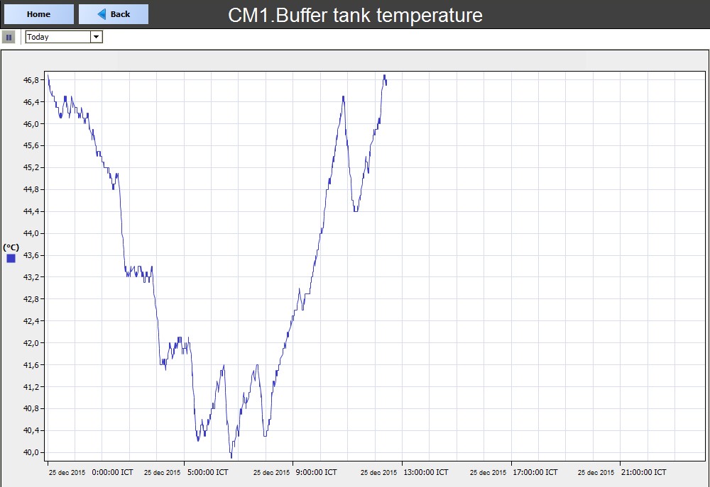
All history data is stored on panel computer’s storage device for 1 years. Older data is automatically deleted to save storage space.
Also, users can view list of all active alarms, or to view history of alarms.